|
Severe Paralytic Scoliosis |
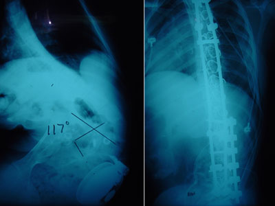
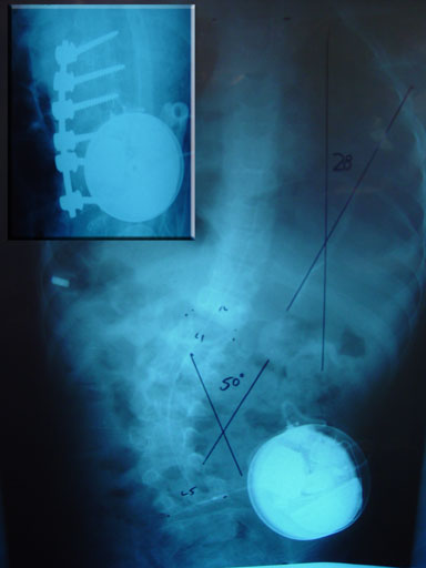
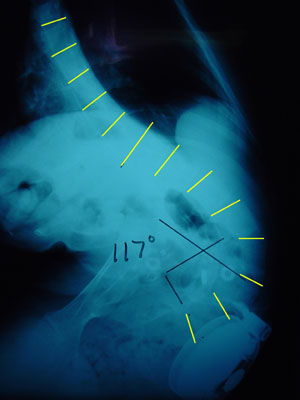 This is the x-ray of a youngster with severe spasticity and feeding problems whose condition rapidly worsened as other medical problems delayed and hindered her care.
A supine image with her lying in as straight a posture as she is capable, shows that her spinal curve is stiff.
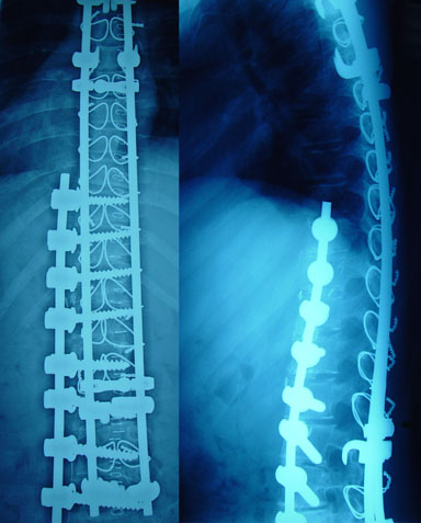
A feeding tube allowed some weight to be gained, as she had been nearly skin and bones. You can appreciate that she has had many surgeries.
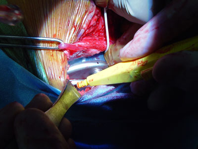
A Baclofen pump is, unfortunately, situated right in the path of her spinal surgery.
 |
Part I - Anterior Spinal Fusion
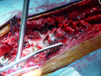
From a side incision, in a side lying position, the pump is removed and set aside as the front of the spine is exposed.
 |
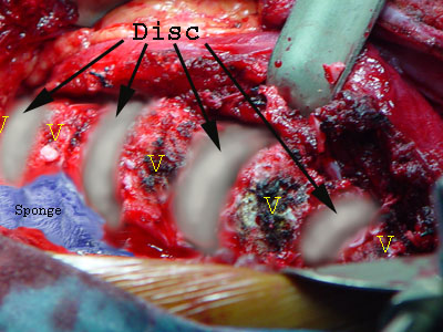
For ease of understanding, the discs portions of the vertebral column (as seen from the front) are artistically enhanced here in gray-white.
Vertebrae are labeled 'V'.
Organs are pulled aside and the psoas muscle and diaphragm peeled off the spine.
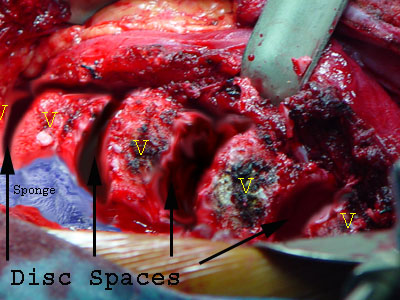 Here the disc spaces are depicted with the disc structures totally removed - right down to vertebral bone.
Ribs that articulate between
adjacent vertebral bodies are trimmed back a bit in order to free up movement between adjacent vertebrae.
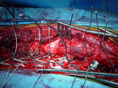
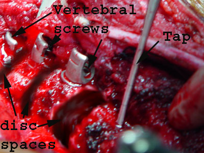 Each vertebral body is diagonally tapped for cross-diameter length then affixed with a screw bearing a specialized head that can accept a rod. S
The specialized screw heads can be angled.
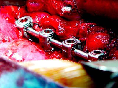 A rod is placed into the row of cup shaped screw heads and secured. That rod is contoured, rotated and screw distances adjusted until the desired spinal
shape is attained.
A rod is placed into the row of cup shaped screw heads and secured. That rod is contoured, rotated and screw distances adjusted until the desired spinal
shape is attained.
What is left of each empty space is filled with chips of bone taken from the ribs.
Thus the vertebral bodies will "fuse" to one another (become bridged by bone).
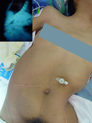
The Baclofen pump is replaced as the surgical exposure is closed. The pump will be reprogrammed later (after surgery). For now, the pump is primed with saline.
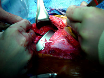 |
Notice also , in the above image, the thin white tubing which comes off the pump. That tubing which carries the drug dives into the body fat traveling around the waist to reach the back side of the spine.
The front wound is closed
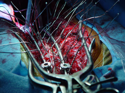
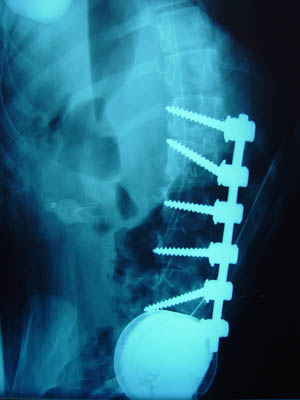 So far, so good. Diverging screws provide powerful corrective forces in the worst curved part of the spine.
The baclofen pump is back to where it began (large white circle at bottom).
Part II - Posterior Spinal Fusion
The patient is now placed prone (back facing up).
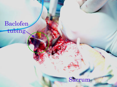 Exposing the back side, the pump tubing is protected where it enters the spinal column.
 The back side of the spine is exposed (head toward left). The pump tubing is seen. The butterfly shaped posterior parts of the vertebral column are also seen.
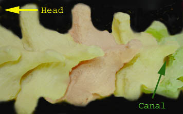 This model of the spine shows the approximate view as seen in the image above (head end toward left). Individual vertebra are tinted for ease of
identification). The open spinal canal which is seen in the model is sealed by a tough yellow ligament (ligamentum flavum) in the actual spine. That ligament gets windowed to allow wires to be passed beneath the bones seen here. The
wires get formed into loops which embrace the metal rods. This wire loop manner of grasping the spinal bones was developed by Professor Luque of Mexico.
This model of the spine shows the approximate view as seen in the image above (head end toward left). Individual vertebra are tinted for ease of
identification). The open spinal canal which is seen in the model is sealed by a tough yellow ligament (ligamentum flavum) in the actual spine. That ligament gets windowed to allow wires to be passed beneath the bones seen here. The
wires get formed into loops which embrace the metal rods. This wire loop manner of grasping the spinal bones was developed by Professor Luque of Mexico.
 Some hooks are placed (extreme left) to grab certain key vertebra. These hooks also have cup-like tops which can embrace a rod.
Small (red) sponges are seen at each level where the ligamentum flavum has been windowed for the placement of Luque wires as the next step.
 Wires passed and shaped so as to help keep them manageable and safe.
Near the right, the cup-like top of another hook is seen engaging a vertebral segment. The threads of the cup-like top of the hook will accept a screw-in locking cap which binds the rod within that threaded receptacle. Once so secured, the hook becomes a rigid part of the rod construct.
 Another view from the head end after two rods were placed into the hooks and secured with locking caps.
Before the caps are locked tightly, the rods may be rotated (rod grabber seen in distance on left).
Certain wires are lightly secured (twisted about the rod) to relieve stresses from the more at risk hooks until the final shape is set.
The metal rods can (and are) reshaped after they are positioned so as to maximize correction and balance. Metal benders specialized to this purpose are used.
 With the wires twisted, trimmed short, and folded down flat against the rod, the final configuration is better seen.
Note the "cross link" which (at two to three levels) binds the two rods into a single rigid construct.
Cross links also maintain distance between the rods which assures that that the spine moves toward the rods and not the reverse.
Wires were set by twisting at the concavities of both sides and working outward. That means from the bottom of one side and from the top of the other. End hooks are adjusted initially so as to be able to slide and accommodate the spinal movement.
Once the shape is set, the hooks are tweaked a bit then locked firmly to the rod with a counter torque setting instrument (locks the set plugs without twisting the hooks).
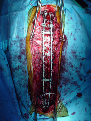 |
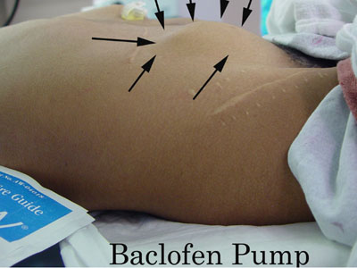
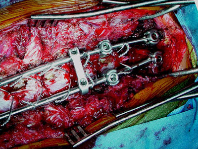
Final pattern (head end at top of image). Everything set. You can see the Baclofen pump tubing near the bottom, coming in from the right.
Details of bone grafting follow, and then the wound is closed being careful to maintain the pump tubing as patent (tested by the pump itself primed with a test solution (saline). Drains are secured to avoid the metal.
 |
Time for coffee.
Here are two clinical variations:
(similar potential constructs with different aspects.)
 |
However, this next child - although technically 10 years old - has the habitus of a six year old. The curve is no longer responding to braces but had been held at about 35 degrees for the last several years by paraspinal Botox used to make aggressive bracing tolerable. With that, significant growth and health was gained. Even so, the overall size is still very small. A full length fusion - front and back - at this point will leave a very short chest or a very high risk of late crankshaft deformation if posterior fusion performed alone.
There are many ongoing problems in nutrition and a minor - though for this treatment - a problematic - bleeding tendency.
 |
A front-only fusion instrumentation with nonparallel metal (which lessens the pull out of metal from soft bone risks). This is partial fusion to allow continued bracing and growth. The rest of the surgery will be done as late as curve control allows with as great a size as we can delay for.
The point to be made is that clinical circumstances vary and those details do matter. There is not a single do-it-this-way solution to be broadly applied.
![]()